Remote Control Ceramic Filter Circuit

This circuit acts like the infrared receiver of electrical appliances.
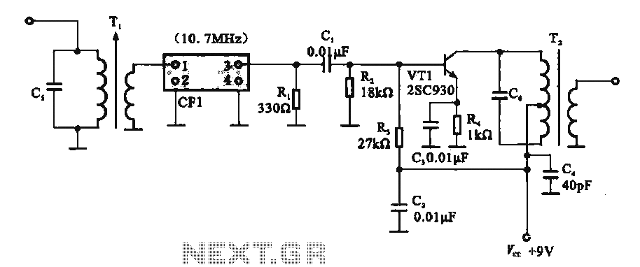
Remote control ceramic filter circuit. Like the two connection ceramic resonator the three connection ceramic filter it is possible to generate an equivalent circuit in terms of the basic inductors capacitors and resistors that might be needed to recreate the rf filter. Ceramic bandpass filter circuit symbol. As the inventor of the ceramic monoblock 1982 cts has a unique intellectual property position which enables us to deliver the best ceramic rf filters. We have used ic 4017 to convert it into a push on push off switch.
A ceramic resonator is an electronic component consisting of a piece of a piezoelectric ceramic material with two or more metal electrodes attached. When connected in an electronic oscillator circuit resonant mechanical vibrations in the device generate an oscillating signal of a specific frequency like the similar quartz crystal they are used in oscillators for purposes such as generating. The proposed infrared or ir remote control circuit can be used to operate an appliance on off through any standard tv remote control handset. Because the human eye cannot see infrared light.
The transmitter is a saw stabilized oscillator with a pcb antenna where a one port saw resonator is used as the basic circuit form shown in above photo the oscillator is. Next we will show a sample application circuit which is 433 92mhz saw resonator enabled ook remote control transmitter the circuit and design can be found at following. 5 bands dual conversion receiver i5tdj. So we use the phototransistor as the light receiver from the remote control.
868 mhz remote control receiver ly3lp. 455 khz to 12 khz drm converter. In this simple remote control tester circuit. Active filters can be used to design high order filters without the use of inductors.
But a phototransistor can detect infrared light. Homebrew rf circuit design ideas there is no such thing as a new idea. In this write up we discuss a couple of these simple infrared remote control circuits designed for controlling any given electrical appliance through an ordinary or tv remote control unit. Receiver circuit is connected to ac appliance via relay so that we can control the light remotely.
In this remote controlled switch circuit we are using tv remote to on off the ac light by pressing any button of remote and using the tsop1738 at receiver end. 1296 mhz superregen receiver ly3lp. Lowest insertion loss il highest attenuation rejection isolation highest q factor smallest size for specified performance highest power handling average and peak and sharpest transition slope. 455 khz to 12 khz drm converter with ceramic oscillator.
