Receiver Noise Floor Calculation

A factor of 1 2 is due to voltage division across source and load resistors and another factor of 1 2 is due to envelope scaling.
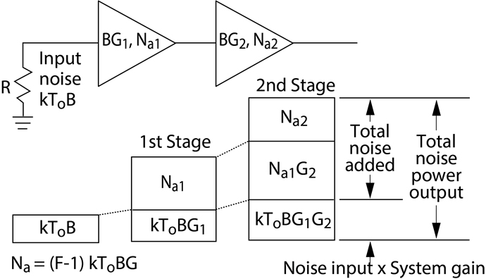
Receiver noise floor calculation. Radio receiver noise floor. The noise power in the receiver intermediate frequency if filter bandwidth that comes from ktb. In practice m is usually chosen to be greater than unity. The sum of the source available noise power n sa and input referred noise of the receiver n i defines the receiver s noise floor.
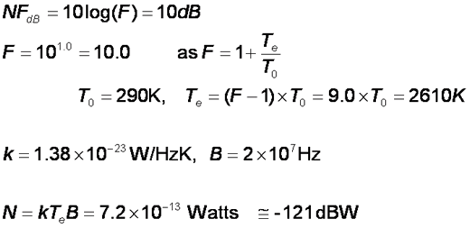
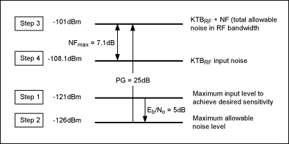
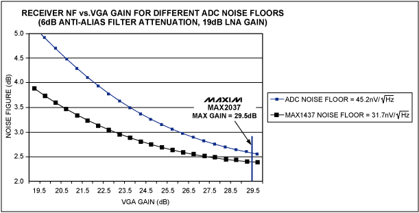
The first is the minimum equivalent input noise for the receiver. See the featured example two tone envelope analysis using real signals for more discussion on scaling envelope signals for power calculation. To calculate receiver sensitivity we add the overall noise figure of the receiver to the noise floor. As shown in the equations when noise figure is low sub 10db p outd gain is close to 170dbm hz.
This is an online calculator that calculates thermal noise power based on temperature and bandwidth. The noise power from a simple load is equal to ktb where k is boltzmann s constant t is. 7 noise floor dbm 10 log n sa n i nf 10 log n sa n sa dbm nf 174 b in db nf for the signal to be detected it must be higher than the noise floor 6. The signal must be higher than the noise floor by the carrier to noise ratio required for a desired signal quality.
To calculate the thermal noise levels there are formulas or equations that are relatively straightforward. Normal lna gain is about 20db. While noise can emanate from many sources when looking purely at the receiver the noise is dependent upon a number of elements. At this point we would like to know the noise floor in our receiver i e.
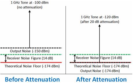
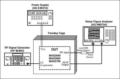
The biggest limitation comes from the noise floor of the spectrum analyzer. The measured noise floor at 177 dbm hz is reduced by 3 db from the specified 174 dbm hz noise floor. Since the units of ktb are watts hz calculate the noise floor in the channel bandwidth by multiplying the noise power in a 1 hz bandwidth by the overall equivalent noise. It can alternately be defined as a signal that produces a signal to noise ratio of a given value m at the output.
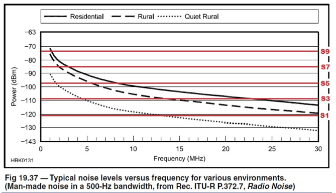
Thermal noise is effectively white noise and extends over a very wide spectrum. In addition to this there is an online calculator to provide additional assistance. This can be calculated from the following formula. Everything rf has the largest selection of online calculators for the rf and microwave industry.
Basic thermal noise calculation and equations. A minimum detectable signal is a signal at the input of a system whose power allows it to be detected over the background electronic noise of the detector system. The noise figure is the difference in decibels db between the noise output of the actual receiver to the noise output of an ideal receiver with the same overall gain and bandwidth when the receivers are connected to matched sources at the standard noise temperature t 0 usually 290 k. In that case we need to measure a noise power density of 150dbm hz which is lower than the noise floor of most spectrum analyzers.

